|
WHOA DID YOU JUST SAY ACTUAL CONTENT!?!?!?! Ok, don't get too excited. Yes, I did actual substantive design drawings. As of yet, nothing is dimensioned since I didn't have calipers with me on my eight hour flights to and from Berlin. Without further ado (and please forgive the poor art and handwriting), here are my preliminary designs. 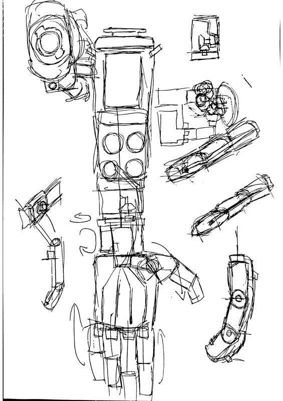 This was my very first (and very rough sketch of what I want the arm to be. The key points to take away are the two position thumb, pan-tilt wrist, and cable drums for spooling our artificial tendons onto. 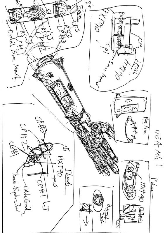 This was my second go around refining that basic layout, and it is currently the mechanical layout I am working from. Big take-aways here are the further elaborated concepts of the fingers, thumb and wrist mount. I frankly dont know how much this could support, but I am shooting for the ability to pick up a 10kg weight using PLA components, so all joints and crosspins either extend all the way through the components in question, or have redundent support. 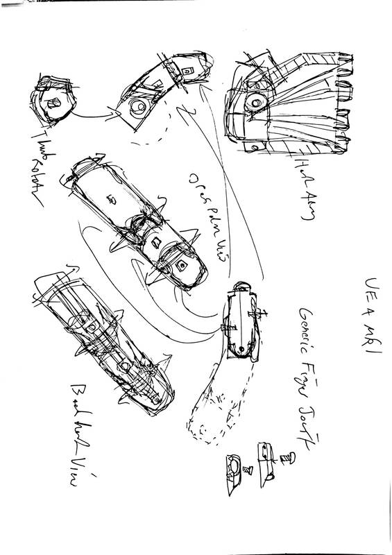 A slightly more detailed look into the fingers, thumbs and hand. The fundamental concept here is to use a series of replaceable and interchangeable joint segments (each of which contains an extension limiter, a clamp for elastics, and a channel for the artificial tendons). The thumb is the same fundamental system as the fingers, but utilizing only 2 of these segments as opposed to 3, and being mounted on an HXT90 servo. The hand has a few pictured cable guides, but not much of note besides that. 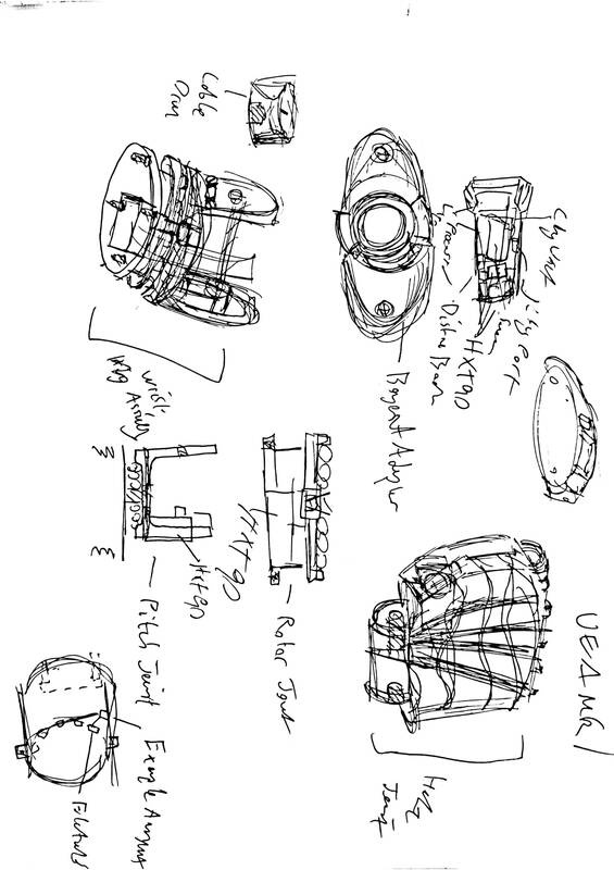 A slightly more in depth look at the custom socket, bayonet mount (interesting name, read the Wikipedia article), the hand, and the wrist pan-tilt unit. 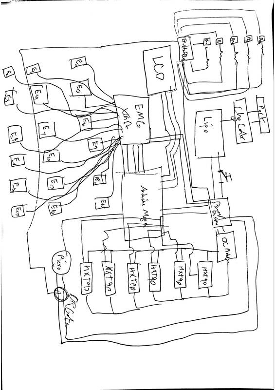 Finally, a very rough, and I do mean VERY rough block diagram. This is roughly what the electronics will be. Effectively, a EMG sensor array will use 3 electrodes per finger (this might be able to be reduced though), this signal is processed by an Arudino and sent into the corresponding servo. This pulls the artificial tendon causing the finger to bend. The servo array pulls its power from a separate distribution board as pulling it straight from the Arduino would cause problems. These are the slightly more in depth exploded views of each part.
As I said, not much. It will of course be on the github in PDF format. Actual CAD to follow.
1 Comment
mary e carsley
8/1/2019 11:50:24 am
A pleasure to read your blog! Keep up the great work! Leave a Reply. |
AuthorMy name is James Falcon Doss. I'm a member of Severn School's class of 2020 and have a passion for all forms of engineering. Archives
May 2020
Categories |
 RSS Feed
