|
You read that correctly, the first version of the arm is done. Modeled and thrown together, it is articulated as previously described, and will be ready for early tests sometime this September-October after initial manufacture. Here are so screen shots of the arm. 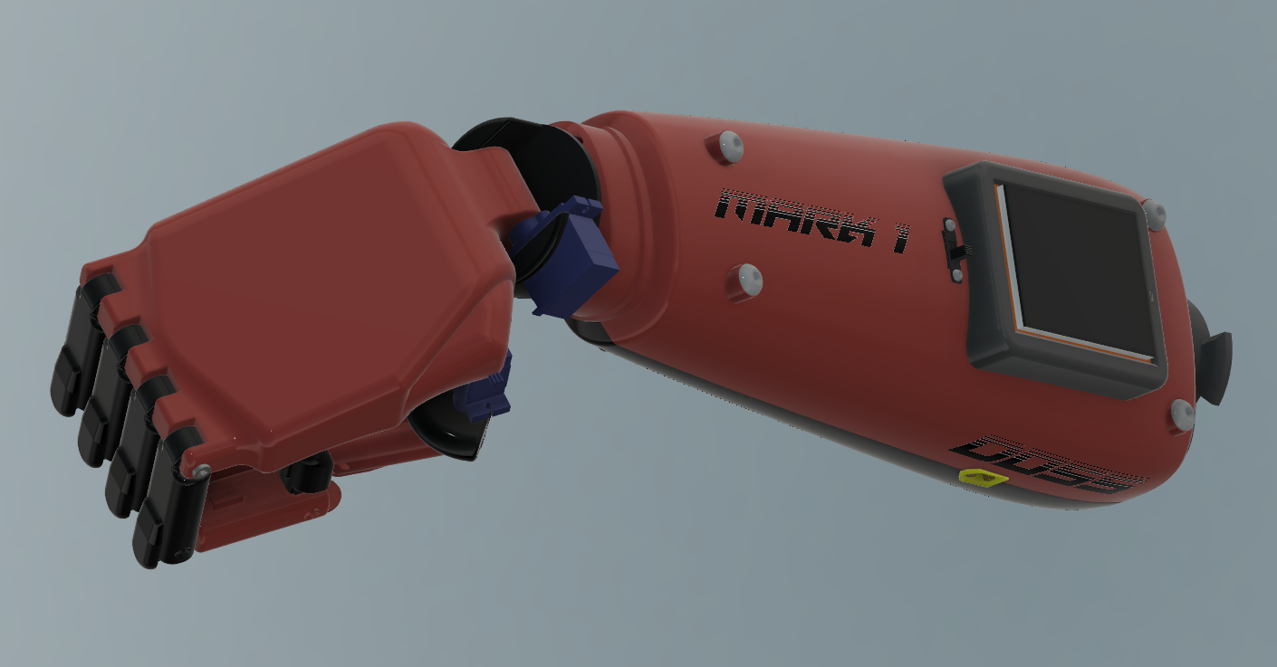 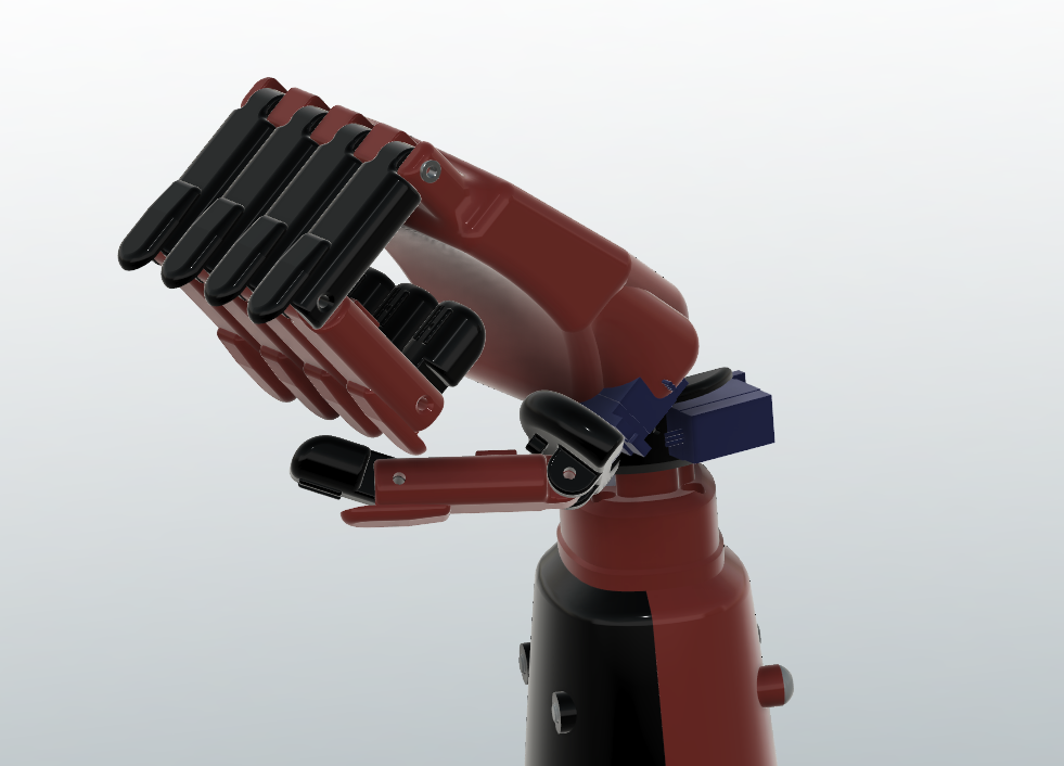 Aesthetically, it was of course inspired by Snake's arm from Metal Gear Solid V (obviously the similarities end pretty quickly because it needs to be functional).
Again, all CAD files will be available on the GitHub page.
1 Comment
Yep, Initial CAD on the forearm is done now. This was not the most mechanically complex part, but being the root of all parts, needs to have to most thought and consideration put into disassembly and maintenance. After a few iterations, version 11 came out to look like this: 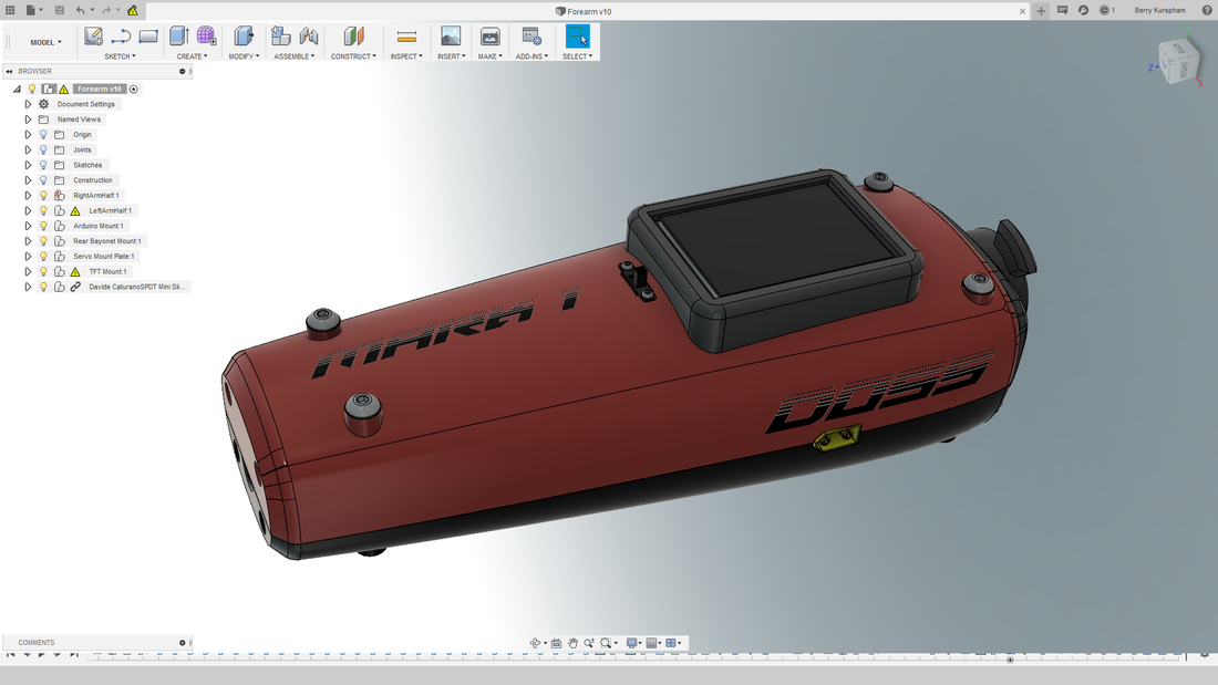 Aesthetically it could use a bit of work, but It's definitely not too shabby. Again, this will be available on GitHub. During the design, I used a number of public GrabCAD designs for reference of common components (HXT90, Arudino Uno, XT60, SPDT Slide Switch etc.), as well as parts from the McMasterCarr Catalog. The names of authors can of course be found in the STP file.
WHOA DID YOU JUST SAY ACTUAL CONTENT!?!?!?! Ok, don't get too excited. Yes, I did actual substantive design drawings. As of yet, nothing is dimensioned since I didn't have calipers with me on my eight hour flights to and from Berlin. Without further ado (and please forgive the poor art and handwriting), here are my preliminary designs. 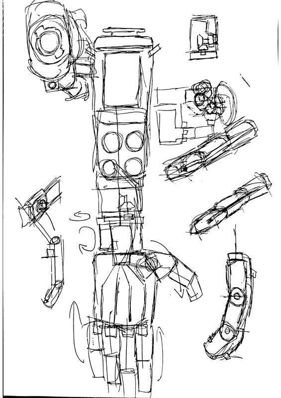 This was my very first (and very rough sketch of what I want the arm to be. The key points to take away are the two position thumb, pan-tilt wrist, and cable drums for spooling our artificial tendons onto. 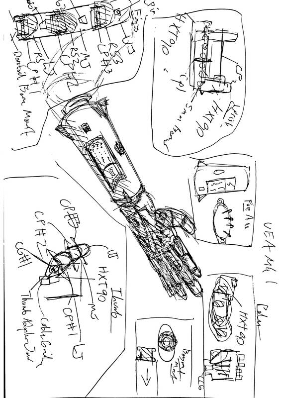 This was my second go around refining that basic layout, and it is currently the mechanical layout I am working from. Big take-aways here are the further elaborated concepts of the fingers, thumb and wrist mount. I frankly dont know how much this could support, but I am shooting for the ability to pick up a 10kg weight using PLA components, so all joints and crosspins either extend all the way through the components in question, or have redundent support. 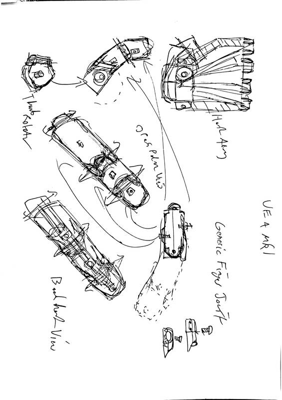 A slightly more detailed look into the fingers, thumbs and hand. The fundamental concept here is to use a series of replaceable and interchangeable joint segments (each of which contains an extension limiter, a clamp for elastics, and a channel for the artificial tendons). The thumb is the same fundamental system as the fingers, but utilizing only 2 of these segments as opposed to 3, and being mounted on an HXT90 servo. The hand has a few pictured cable guides, but not much of note besides that. 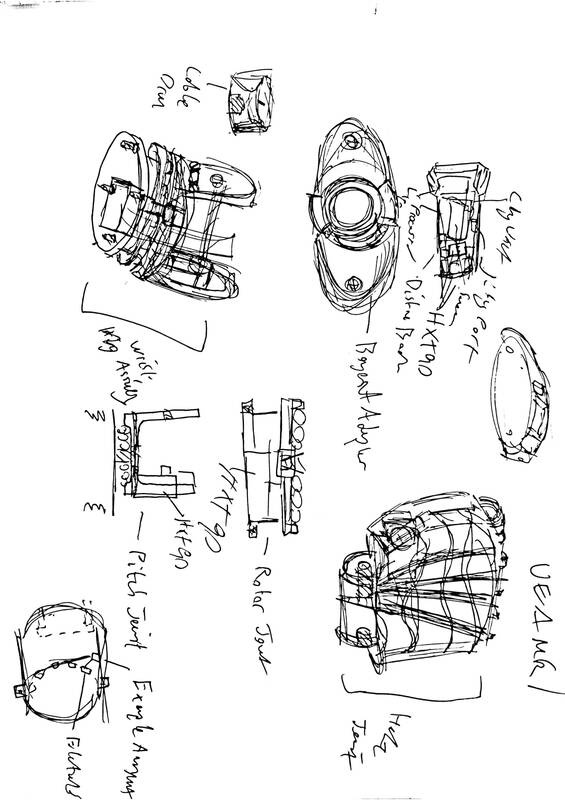 A slightly more in depth look at the custom socket, bayonet mount (interesting name, read the Wikipedia article), the hand, and the wrist pan-tilt unit. 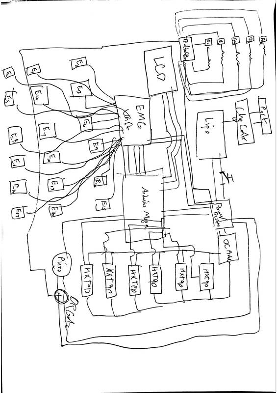 Finally, a very rough, and I do mean VERY rough block diagram. This is roughly what the electronics will be. Effectively, a EMG sensor array will use 3 electrodes per finger (this might be able to be reduced though), this signal is processed by an Arudino and sent into the corresponding servo. This pulls the artificial tendon causing the finger to bend. The servo array pulls its power from a separate distribution board as pulling it straight from the Arduino would cause problems. These are the slightly more in depth exploded views of each part.
As I said, not much. It will of course be on the github in PDF format. Actual CAD to follow. Whew, all caught up! Now we are back to modern times. Fun fact about today, exactly 50 years ago, Apollo 11 and the Eagle LM and Columbia CSM departed for the moon. Anyways, back to the arm. This week wasn't exactly riveting design work, but it was critical research.
I'm going to be trying to build a replacement for a human arm, so I should get to know the general anatomy of the arm a little bit better. So far, I've been reading through a myriad of anatomy textbooks and 3D models of the human skeleton. A interesting resource I didn't think to check (until my sister suggested it) which has in fact, been surprisingly helpful has been figure drawing books. My favorite so far of this collection has been Figure Drawing For All It's Worth by Andrew Loomis. While the process of modelling and drawing a hand are entirely different (mainly because you can rely on measurements to thousandths of inches, therefor you don't have to work from general to specific as you would when drawing, It has greatly aided in my preliminary sketches of the arm. Slowly I'm approaching a "final" pre-CAD design. I'll elaborate a bit... -The arm will use 5x 9 gram PWM servo motors to control bend of each individual finger with and additional 2x servo motors being used to control the 2D positioning of the thumb. -20lb fishing line and or kevlar thread will serve as the tendons of the hand. -Elastics will be stretched along the back of each finger through a series of braces to return each digit to an extended position when so controls are applied. -Rotation and flex of the wrist and will be provided 2x high torque servo motors mounted in a standard gimbal assembly. -XT-60 and 3 wire communications connectors will be used to transfer all relevant control information from the forearm to the hand. -The forearm will include a 2700 mAh 3S LiPo battery and integrated discharge protection circuit as well as the micro controller which will be interpreting and processing signals. -A standard "bayonet" type mount will secure the arm to the socket. below the elbow. Lots of boring words that don't mean much without some drawings to demonstrate them. I'll be working on those on my two 8-hour plane trips in the next week. Who doesn't wish they had more of it... Yet when time opens itself up, we tend to squander it. Why do I delve into philosophy in what should be a technical blog? Who knows, maybe it reveals some repressed emotional programming within me, or maybe I'm overthinking it. Someone get Freud on the line. Anyways, back to the arm. Any serious engineer needs to often consider the fit and function of parts before constructing them. It isn't always feasible to construct prototype after prototype until you can nail dimensions and part design, especially for a mechanical assembly as complex as an analog for the human arm. Enter computer aided design or CAD. I've been using CAD for about 5 years now, starting with simple 2D programs, and progressing through Onshape, Solidworks and finally have arrived at Fusion 360. Now why Fusion you ask? No grand reason, I forgot the Solidworks license information I was given by the school. However Fusion 360 has some very interesting things going for it. For one, it's so much better on the eyes. I mean would you rather stare at this... 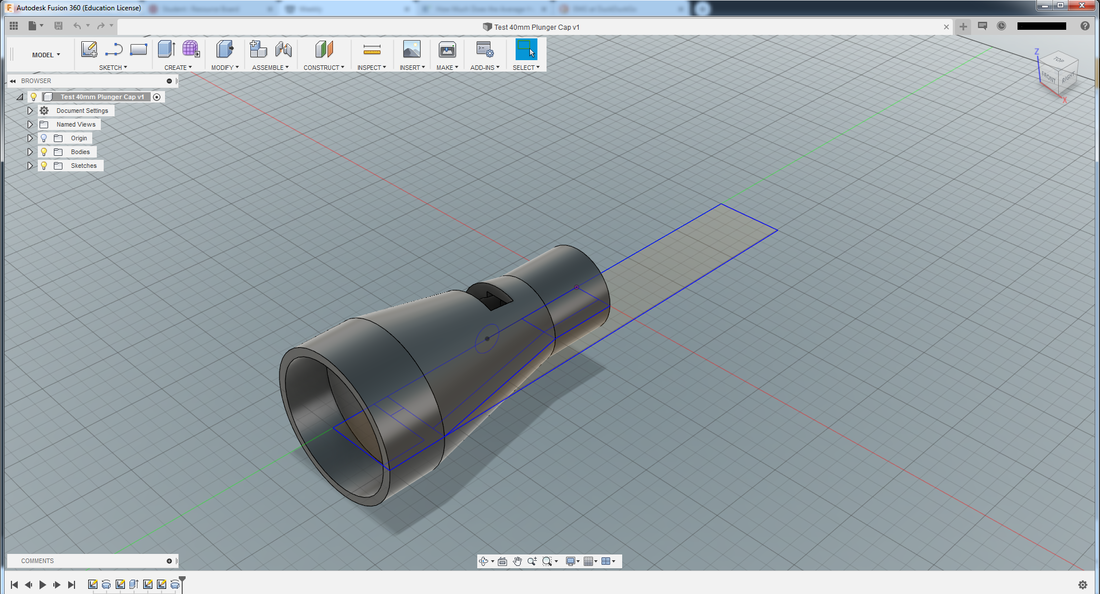 Or this... 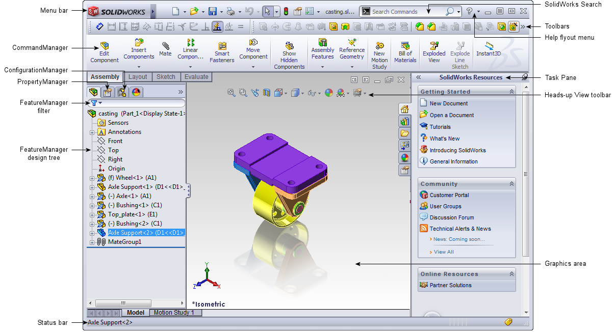 For 8+ hours on end? Yeah I thought so. Fusion also has one other major advantage over it's competitors, that being Autodesk's licensing policy. Whereas Solidworks must be purchased by any individual or corporation regardless of usage, Fusion offers free, full licenses for students and educators. Of particular interest in the included educational license is a full simulation suite. While running cloud simulations costs a fair chunk of change, client-side simulation is always free, providing you have the hardware to run it. Hurray for impulse buying an i7 last year! This is also another late blog post... whoops ¯\_(ツ)_/¯. Anyways, for the second half of June, I was familiarizing myself with yet another CAD software. Fusion is a fairly standard parametric modelling program, so it's not too huge a jump, but things like assemblies and component construction is entirely different. Anyways, I'll end by showing you all how pretty a complete and total part failure under 500lbs of force in Fusion looks... 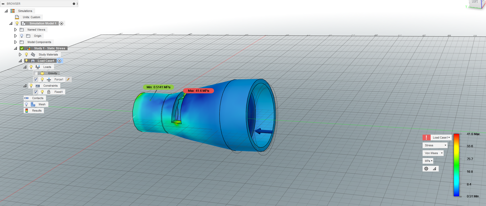 "It was not in their blood, It came to them very late, with long arrears to make good the English began to ha..." - wait, wrong Beginnings. Sorry.
In the interest of honesty, I will admit, in the midst of working on UAS autopilot development for the U.S. Navy and Coast Guard, I kind of forgot about writing these blog posts. My bad. Anyways, I'll be recapping what I worked on for the first half of June. Coming into the fellows project, I had a good idea of the course I wanted my project to take. After coming out of it, and having talked to my fellow Severn Fellows, I had a wealth of new ideas and directions to go. After mulling over the specifics of my project, and the potential options and goals to pursue, I set about constructing a requirements list as I do for any major endeavor. The fundamental goal of this project is simple; to make a generic, low-cost myoelectric prosthetic capable of fine and coarse motor control. Practically this means the following: -A complete replacement for the lower arm (below the elbow) being capable of all major joint movements. -A total cost not to exceed $200 per unit (excluding labor). -A mass not to exceed 4kg. -A fast charging, modular and easily maintainable mechanical construction. -Capable of individual finger movements and two axis thumb positioning either through electromyography or motion capture of the opposing hand. -"One size fits all" - i.e. only the socket for mounting the arm to the root of the severed arm should have to be custom fit. Overall, an ambitious project sure. But certainly achievable. In the following posts, more specifics behind my design philosophy and research will follow. |
AuthorMy name is James Falcon Doss. I'm a member of Severn School's class of 2020 and have a passion for all forms of engineering. Archives
May 2020
Categories |
 RSS Feed
